1/4 Wave Ground Plane
Categories: Hacking
I’ve had a plan to build a 1/4 Wave Ground Plane antenna based on this calculator and the data available on that site for some time.
I’m doing the 2m band first (144MHz) - I’ve got piece of 4mm brass diameter pipe for my driven element, and 6mm aluminium pipe for my radials. The radials are to be angled at 45° from each other, at 45° below normal. Click the link for what that looks like!
The linked website has a variety of methods of holding it all together - I have opted for an aluminium plate for mounting everything to, but I wasn’t too keen on the suggestion of using a cut up chopping board for vertical stabilisation on the driven element.
I figure it’d be a fun challenge to 3D print something. I’ve never designed an object myself and printed it. People tend to make it sound easy - ‘oh i printed that, it was fine’.
Let me clear this up: 3D printing is hard. There is a whole world of terminology, incompatibility and more to learn about. There’s loads of good information and misinformation online, and learning to sift through it is a challenge.
Attempt 1
I figured I’d make a pyramid, which captures the RF connector, screws, bolts and gives some horizontal support to the driven element.
I set to work in OpenSCAD, having looked through FreeCAD and decided it was far too much work to learn.
OpenSCAD has great documentation on wikibooks and is easy to get to grips with if you’ve used a c-like language before. Quickly I had used an example from the book to get a pyramid like polyhedron, thought out some dimensions and made an object!
When I went to print it, the Hacklab 3D printer and I fell out very quickly, and no printing was done.
I came back another week and in the end I had the result in the cover image up top.
It’s a little too small on all sides, and the all the cutaways for the connector, bolts and tubing are too small. I think theres a little gap between my understanding and reality here, but it’s a start.
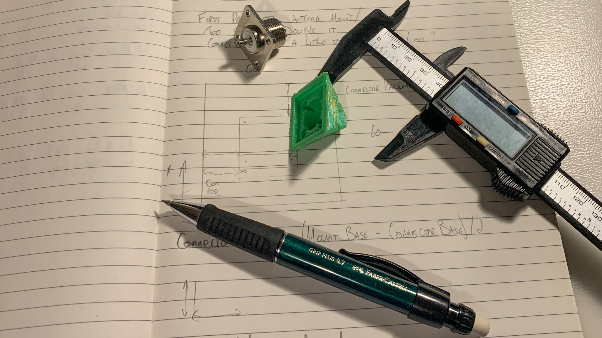
I took it home, got the callipers out and got to work designing V2.
Attempt 2
Attempt 2 is much larger (50x50x50), and has some tolerance built in for printer weirdness. The shape is significantly changed from a pure pyramid to a pyramid sat upon a box section, which will hold the ground radials.
Once the print had started, I very quickly had some problems:
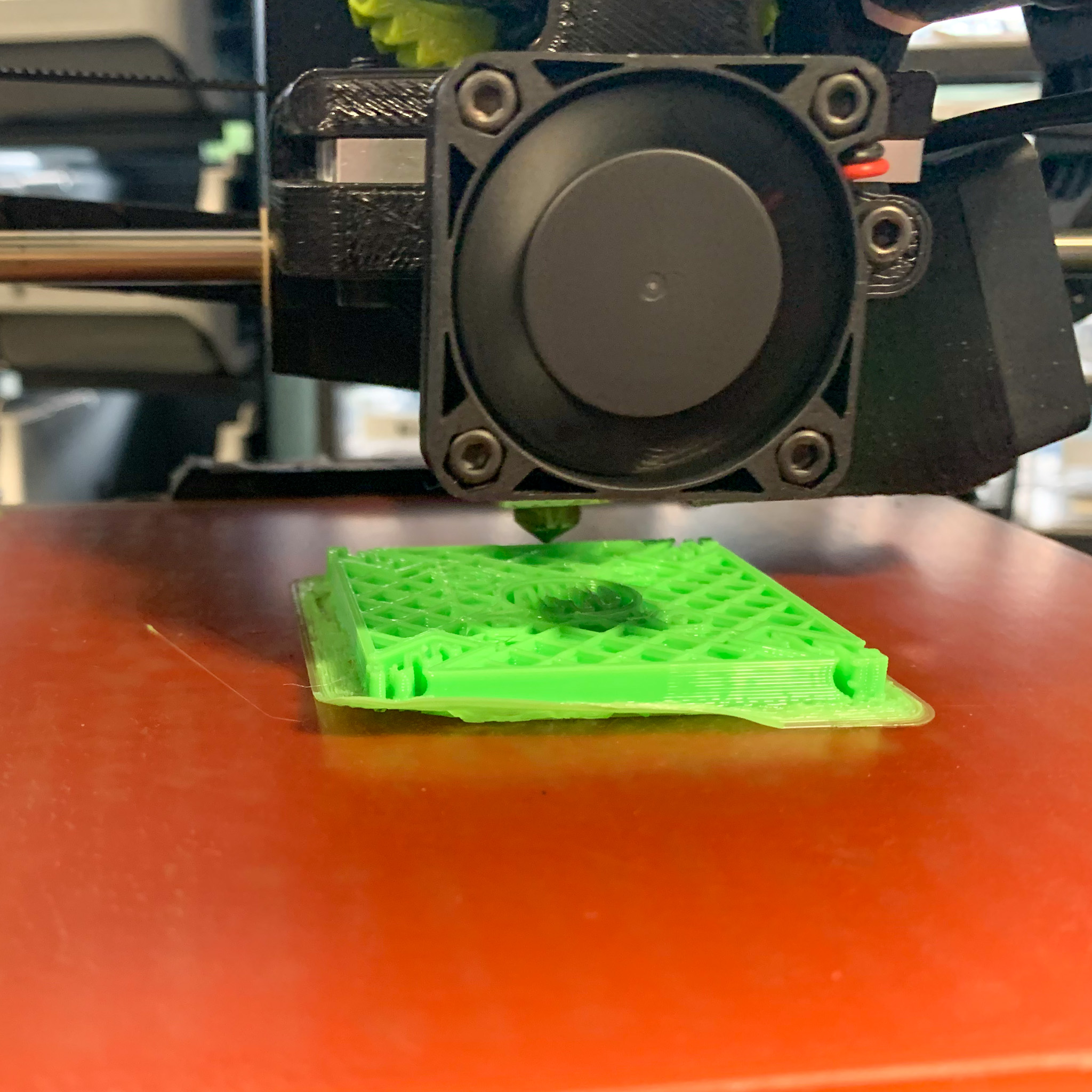
Talking to others in the hacklab, the streaks and melt suggests over-extrusion and/or the first layer flowrate / heigh being wrong. I remember in the depths of my mind that the default profile for cura-lulzbot is 2.85mm and the filament we were shipped is 3mm. That might explain it.
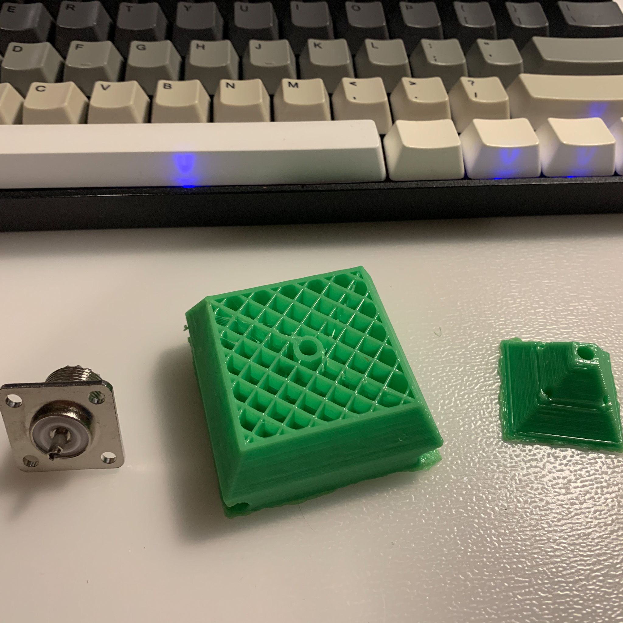
I cut the print at 69% (nice), so I could test, assemble bits together and work out what I was doing wrong. The connector now fits, however the bolt holes are out of alignment still. tj has suggested making a negative of the connector to use in openSCAD - that might be a wise idea! I’ll need to find some plans of an SO239 connector and make sure they match. The ground radials mostly fit, but needed a push. As it’s not vital for them to be a snug fit, I’ve upped the diameter.
The outcome of the print, alongside the connector and the small V1 can be seen below.
Conclusion
I will concede that 3D Printing isn’t that hard to get into once you get started and get your head round the basics. It mostly needs time and space to think round volumetric problems.
Attempt 3 will be printed with more appropriate extrusion and maybe will look better - the final version will be a much much finer resolution, and hopefully all these kinks will have been ironed out by the time I hit that print. I’ve also been reading a book with some neat design ideas which I’ll be incorporating.
Everything would have been faster if I had the printer at home to iterate quickly, but actually having to take a break, measure things, redesign on paper and then rebuild probably led to a better design.
Hopefully I’ll have the finished antenna in the next post!
Tags: Radio 3d Printing Linux