ESP8266 First Steps
Categories: Hacking
So, I’ve been slowly working on the lights in the hackerspace. I’ve rewired them using Weidmuller WDU2.5 terminals on DIN rail, as this is what I use in work. It’s a pretty great system and lets me have clean wiring, easy to read wiring and things will probably be safer.
The next steps I’d like to take are to implement the Internet of Shit on our LED lamps above the main workspaces. Because these are lights and need to be used by real people, they cannot be solely internet connected, that would be ridiculous. This means I’ll need to consider per-LED-BANK physical buttons to compliment my software implementation. We’ve got 4 banks of LEDs, so 4 inputs and 4 outputs will be needed.
I’d like there to be a web control panel, but only have it accessible from the 172.32.40/ 22 subnets. The last time we had something that we could access easily from home, we abused it until someone broke it. This is why we can’t have nice things… Even if it was hella fun.
My first idea was for a raspberry pi - this would be fine, if the Pi was more easily network connectable, and didn’t have a ~30s delay before it booted in to my software (give or take).
These excuses mean I get to try an ESP8266 - tj has been banging on about them and my curiosity has piqued.
Step 1 - How do I Power Lights?
So, I’ve got some LEDs. 5050 strip RGB LEDs are my test subjects, because I’ve been fidgeting with them for ages. In reality, the hackerspace lights are not (yet) RGB LEDs, so I only have to worry about 1 channel per bank. For the purposes of testing though, I’ll go full RGB and strip shit out later.
The 5050 Strip operates at 12V, so I need some way to get the microcontroller output to control 12V - it will only provide 3.3V. Typically, we’d use some sort of switching hardware to glue the two bits together… a relay or a transistor.
My chosen transistors are IRLZ34N MOSFETs - capable of switching up to 55V and 30A, with a gate threshold voltage of ~2V, and a nice low gate current.
They were connected in the follwing configuration:
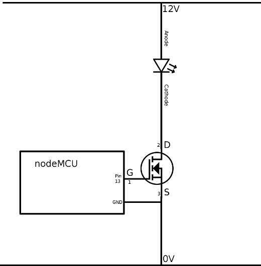
I’ve highlighted the pins on the MOSFET as I struggled a bit finding the relevant information in the documentation. The ground of the nodeMCU/ESP8266 must be tied to the ‘source’ pin of the MOSFET, so the grounds are equal.
In this configuration, the MOSFET will switch on when GPIO Pin 13 is raised high, off when Pin 13 is raised low. This will also happily support PWM for dimming the LED. To run my RGB LED set up, I need 3 channels (pin 12, 13, 14) and 3x MOSFETs. It scales up nicely and works!
Code wise, you can literally use the example code from the micropython documentation and it should work. That’s all I did, more or less. The micropython / PWM isn’t all that difficult.
Here is it working:
You should be able to see my 3x channels on the blue breadboard, and the LEDs cycling through a test pattern.
Thanks to tj’s gif guide for my first bloggable gif.
Next Steps
Next up, I need to get my LEDs powered by MQTT. Early experiments indicate this is going to be pretty do-able. MQTT will be th message bus and allow us to control the lights from the webpage or other devices. Hopefully I can set up a reasonable MQTT set up within 57N.
Also, we need to take input from button(s) and, hopefully, publish that information on the MQTT bus also!
Tune in next time, kids, and see the hilarious continuation of me being average at simple tasks!
Tags: Hacking Hobbies Programming Electronics Internet of Shit MQTT